
Technical article
Machining duplex and super duplex: long components, deep channels and residual stress
Machining duplex and super duplex requires control of cutting forces, residual stress and chip evacuation. Two practical examples show why the machining sequence matters.
Duplex and super duplex are used where standard stainless steel, such as 316L, cannot provide the required combination of strength and corrosion resistance. Examples include subsea systems, seawater valves, desalination plants and chemical processing. Those properties also make the material demanding to machine. For long components, thin sections and deep channels, the challenge extends well beyond choosing a cutting speed.
Direct answer
Why does duplex require a different approach?
Machining duplex combines high cutting forces, work hardening and tool wear. Long components introduce the additional risk of distortion. A suitable approach combines stable cutting with a considered machining sequence, controlled workholding and inspection between operations.
What makes duplex difficult to machine?
Duplex 1.4462 has an austenitic-ferritic structure, usually in roughly equal proportions. Its proof strength is approximately twice that of solution-annealed 316L, depending on product form and supplied condition. Super duplex grades, including 1.4410 and 1.4501, are more highly alloyed and generally place even greater demands on machining.
On the machine, this means high cutting forces and a heavily loaded cutting edge. The material work-hardens as it deforms: if the tool rubs instead of cutting properly, the next cut becomes more difficult. Heat also needs attention. Compared with many unalloyed steels, duplex conducts heat less readily. Cutting data, tooling and cooling therefore need to work together.
A practical example: a curved manifold block
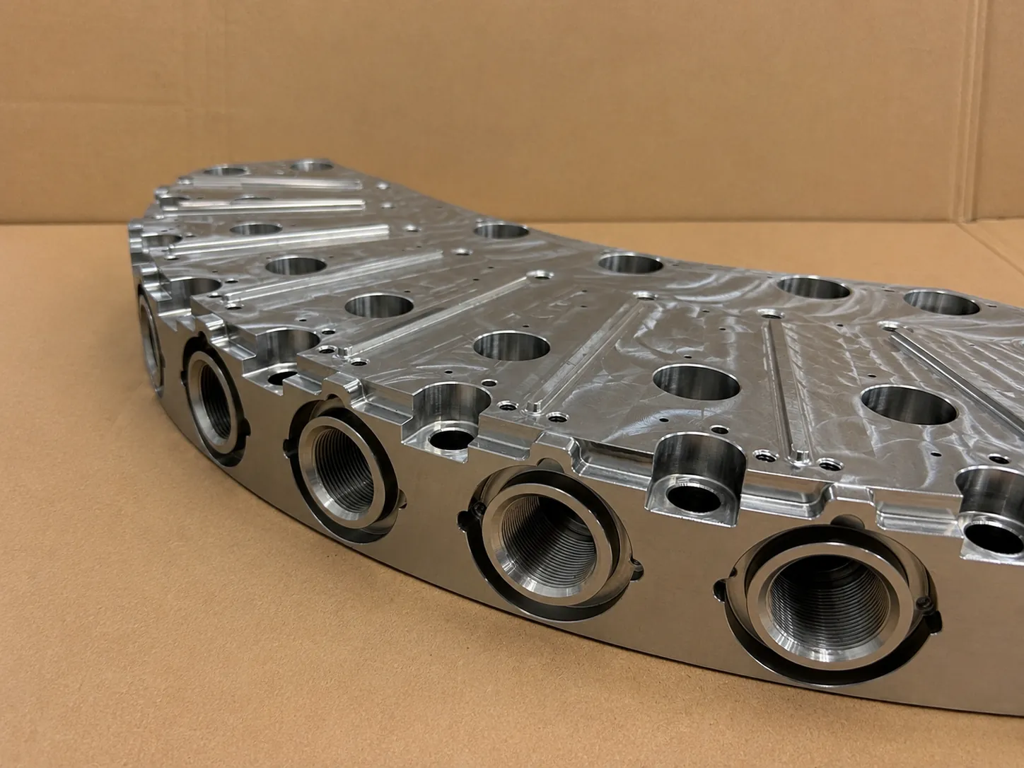
The manifold block in the first photograph is a curved segment with large threaded ports, sealing faces and several bores. With this geometry, connections and faces must remain correctly positioned relative to each other as material is removed from different directions.
Deep, intersecting channels add a second consideration. The outside is accessible for tooling and inspection, while the internal intersections are difficult to reach. The sequence of drilling, finishing, deburring and inspection therefore belongs in the preparation stage.
A practical example: a long cover strip
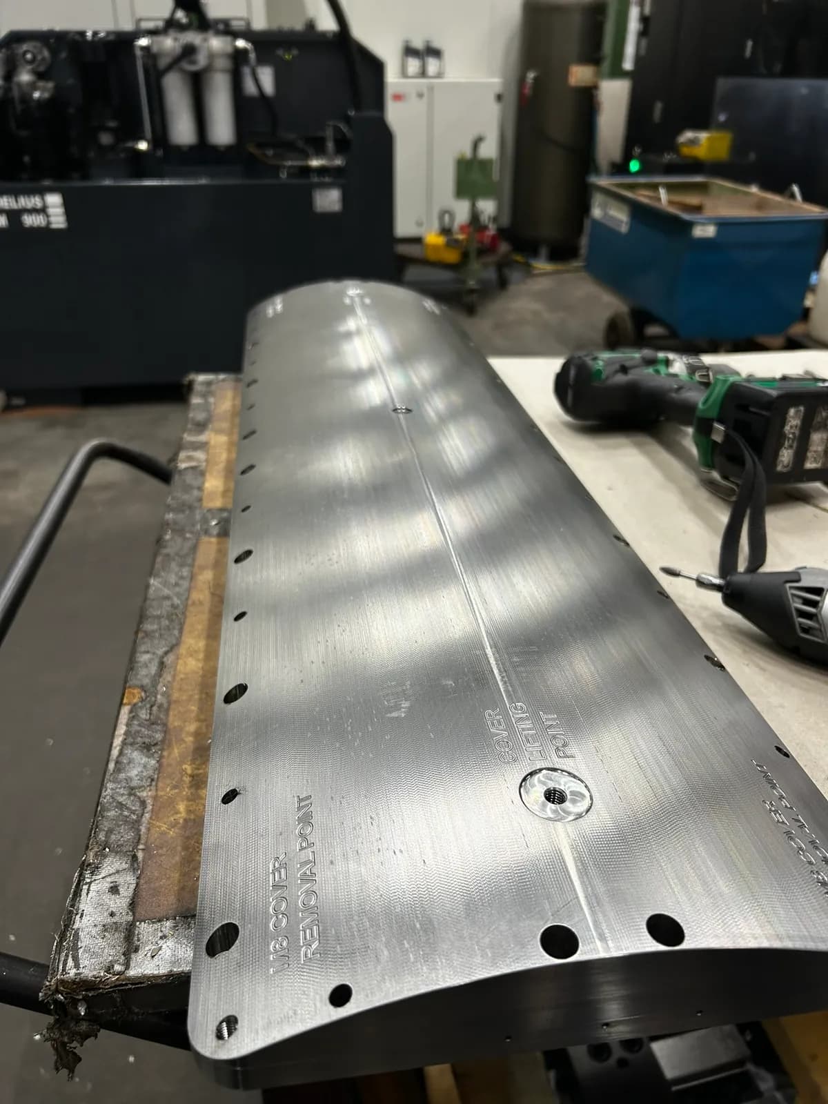
The second photograph shows a long cover strip with a curved surface, a series of holes and engraved markings. Its combination of length and a relatively thin section makes support during machining important.
A workpiece can appear correctly positioned while clamped and still distort after release. The dimensions during milling are therefore only part of the assessment. Its unloaded shape and the hole positions relative to the agreed datums also matter.
Residual stress: the sequence matters
Bar, plate and forgings can contain residual stresses. Removing substantial material from one side changes the stress balance and can cause the workpiece to bend. The extent of distortion depends on factors including the initial condition, geometry and amount of material removed. Whether a few tenths of a millimetre are acceptable depends on the drawing.
For such components, we work in stages. First, rough-machine several sides as symmetrically as the geometry allows. Then release the workpiece, measure its unloaded shape again and adapt the support and workholding accordingly. The fixture must not unknowingly force the component into the desired shape.
Finish-machine to size afterwards, retaining sufficient machining allowance for the critical faces. Releasing and re-clamping is not stress-relief heat treatment and does not automatically remove all residual stress. It reveals distortion and helps adapt the next operation to it.
Deep channels: coolant, chips and burrs
Deep holes require a stable drilling setup and a coolant supply that reaches the cutting zone. Through-tool coolant can help; pressure and flow must suit the tool, hole depth and material. A trapped chip can increase loading, damage the surface and lead to tool breakage.
Where channels intersect, tool support changes and burrs can form. These are difficult to reach internally. For channels carrying a hydraulic or process fluid, deburring, cleaning and inspection must therefore be separate planned steps in the manufacturing route. A clean exterior does not demonstrate that internal channels are free of chips and burrs.
The complete route: from material to handover
Preparation for duplex starts with the exact material grade and supplied condition. Where a 3.1 material certificate is specified, the link between certificate and material must remain intact, including after cutting to size. Marking and any transfer of identification must follow the applicable procedure and authorisation.
Turning, milling, deep-hole drilling, cleaning, inspection and assembly need to be coordinated. We therefore discuss the required operations, critical features and handover documentation in advance. Duplex requires a machining plan based on material behaviour and component function.